Power over Ethernet (PoE) is a term used to describe a set of standards that allows DC electrical power and data to be transmitted simultaneously along the same cable. This standard was first standardized in 2003 with IEEE802.3af and has been updated 2 more times since with the most recent, IEEE802.3bt, being ratified in September 2018. For the purposes of this post, the focus will discuss PoE as it relates to Access Points (AP).
Wired Requirements for PoE
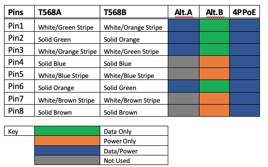
The wattage is delivered to the receiving device using one of three methods: Alternative.A (Alt.A), Alternative.B (Alt.B), or 4PairPoE (4PPoE). Alt.A transports power on the same wires as the data, using a technique similar to phantom power, which is used in traditional landline phone systems. The technique used by PoE transmits two complementary electrical signals at once and is interpreted as different signals by the receiving circuit. Alt.B transmits the electrical power on the pairs of wires that are unused in the transmission of data on the ethernet cable. 4PPoE provides electrical power using all four pairs of wires; this method allows for higher power usage by the end device. A visualization of these three methods is shown below with labels for T568 A and B punchouts.

The initial standard, Type 1 (IEEE 802.3af-2003), initially allowed devices to output a theoretical maximum of 15.4W of DC power. However, some power is lost in the cable when it approaches its maximum length of 100m. It also should be noted that this standard can be used with Cat3 (maximum of 10BASE-T networks) and Cat5 cables (maximum of 100BASE-T networks); methods Alt.A and Alt.B are compatible with this standard.
The next iteration, Type 2 (IEEE 802.3at-2009), allows a theoretical maximum of 30W of DC power that can be sent to the end device; the length restriction mentioned prior still applies, however, the increased power causes more heat to be given off (up to 5⁰C or 41⁰F) and should be a factor in longer runs. This standard is backward compatible with Type 1 devices, though, Cat3 cabling cannot be used due to the higher power output, and Cat5 or greater cable are the only cables that can be used on this and future standards, as this added support for 1000BASE-T networks; Alt.A and Alt.B are compatible with this standard as well.
The Type 3 (IEEE 802.3bt-2016) iteration introduced the 4PPoE method and supports a theoretical maximum output of 60W of DC power and an increase in heat being dispersed by the cable (up to 10⁰C or 50⁰F). The Alt.A and Alt.B methods are still supported in this standard.
The Type 4 (IEEE 802.3bt-2018) iteration is the most recent iteration implemented at the time of writing and uses 4PPoE exclusively because the maximum wattage that can be delivered theoretically is 100W of DC power to the end device. Type 4, being the most recent iteration, has not been implemented widely yet as this type allows support for 2.5GBASE-T, 5GBASE-T and 10GBASE-T. In order to see the full potential of this type, Cat8 or higher cables are required. While the heat output remains the same at 10⁰C(50⁰F), planning cable runs with this temperature in mind is required due to the large amount of current being delivered.
A chart of these four types is featured below to try to provide a better visualization.

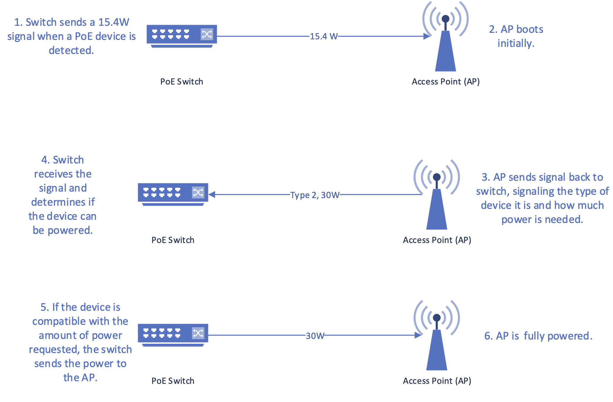
In order to reduce the chance for devices to become inoperable due to more wattage being delivered than is required, the power source and end device sends basic information using the Link Layer Discovery Protocol (LLDP). LLDP is a layer 2 vendor neutral ethernet protocol that is used in network monitoring and network management applications; this protocol was first specified in IEEE802.1AB and IEEE802.3 Sec. 6 cl.79. Using LLDP, the power source determines the maximum wattage the end device can receive, how much power the end device requests, if the device is currently in use, and whether the requested draw on power is more than the power source is rated to output per port. The power source determines this by sending 15.4W initially to the end device to allow it to send a signal back to the source. The initial signal from the end device to the power source identifies the maximum power allowed by the manufacturer and how much power the end device is currently requesting. Once this is received by the power source, it sends the requested amount of power to the end device if it is within the power source’s working limit. A visualization of this process is shown below.

Power Budgeting for PoE for the Number of Access Points
When setting up a PoE network, a maximum power budget needs to be calculated in order to support the most amount of devices; not doing this could cause a switch supplying power to output less power to the connected APs; the issues with this are discussed in Section 4 of this post.
In order to determine a budget for your network, you must first determine the maximum power that can be outputted by a switch. Determining this can be tricky because some switches support adding redundant power supplies, which increases the capacity of PoE for the switch. Once the maximum PoE output for the switch is determined, it is then possible to figure out what type of devices you want and how many you can put on a single switch before less power starts being delivered.
Example: A 16-port switch supports PoE of 246.4W that can be outputted to devices. The switch supports up to Type 3 series of devices or devices that require up to 60W of power to operate. In order to determine the maximum power budget, simply divide 246.4 by 60 and come to the maximum of 4.11, or four Type 3 series of devices with a small amount of buffer to handle power fluctuations. The switch can still function as a normal switch to the other 12 ports, but it cannot provide PoE to those ports without an additional power supply. In order to gain more devices on this switch at once, a lower device type will need to be chosen, which may limit total network speeds or how many end user devices can be connected to the APs at once. Choosing a Type 2 series of devices allows PoE to be used and results in eight ports maximum being used; choosing a Type 1 series of devices allows all 16 ports to be used.
If adding a PoE device to a switch after the initial calculation and determining the current total power output, simply type a command into the switch to display the total PoE output for the switch and calculate how much of the maximum power is left for use. An example of this is shown below and was captured using a Cisco 3560 X PoE switch and a Cisco 3780 B AP. Be aware that this switch uses class of device instead of type of device, but the terms can be used interchangeably in this case.

Not calculating the current wattage being used can affect other devices already connected to the switch by reducing the total power they receive; therefore, it is always important to determine this before adding a new PoE device.
Potential Issues if PoE is Not Enough for the Network
PoE can be potentially detrimental to a network if the end devices on the network cannot receive the full amount of power. This can potentially be an issue if the cable runs are approaching the maximum length (100M) for which ethernet cables are rated to function, as heat starts to build up and degrade the amount of power being transmitted across the cable. Heat in the area surrounding the cable is potentially another factor that affects how much power is transmitted through the cable. One final consideration is the type of ethernet cable in use; improperly shielded cables and older standard cables cannot deliver the high wattage used by devices such as access points.
Devices receiving slightly lower power wattage can still function, but not all features will be enabled. An example of this is with the Cisco Aironet 4800 Access Point Series. These can function using 30W from the source instead of the recommended 31W, however, you lose features such as Multigigabit, USB support, and AUX ethernet. Another example would be the Cisco Aironet 3800 Access Point Series. These can function on 25.8W from the source instead of the recommended 30W; in this case you lose access to the USB 2.0 port.
Not planning for this potential loss in power could severely limit your wireless network in both its performance and potential to scale for more users.
Future PoE Standards
The most recent PoE standard (IEEE 802.3bt-2018) was released in September 2018. This standard allowed up to 10GBASE-T to be used, lowered the power requirements for standby devices, and added enhancements to better support Internet of Things devices and applications. At the time of writing, there are no other updates to PoE standards for devices intended for use in commercial or residential buildings.
The only updates that are related to PoE that could be used in buildings are labeled as maintenance for PoE over 2 pairs (IEEE 802.3cq), maintenance for PoE in general (IEEE 802.3cv), and an update for PoE to function better in harsh environments and potentially for long haul runs of up to 1,000M (IEEE 802.3cg).
These are the most recent updates considered for the PoE standard at the time of writing, and it is unknown when these standards are planned to be implemented.


